

UART protocol:
UART stands for Universal Asynchronous Receiver/Transmitter. It’s not a communication protocol like SPI and I2C, but a physical circuit in a microcontroller, or a stand-alone IC. A UART’s main purpose is to transmit and receive serial data.
One of the best things about UART is that it only uses two wires to transmit data between devices. The principles behind UART are easy to understand. In UART communication, two UARTs communicate directly with each other. The transmitting UART converts parallel data from a controlling device like a CPU into serial form, transmits it in serial to the receiving UART, which then converts the serial data back into parallel data for the receiving device. Only two wires are needed to transmit data between two UARTs. Data flows from the Tx pin of the transmitting UART to the Rx pin of the receiving UART:
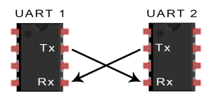
UARTs transmit data asynchronously, which means there is no clock signal to synchronize the output of bits from the transmitting UART to the sampling of bits by the receiving UART. Instead of a clock signal, the transmitting UART adds start and stop bits to the data packet being transferred. These bits define the beginning and end of the data packet so the receiving UART knows when to start reading the bits.
When the receiving UART detects a start bit, it starts to read the incoming bits at a specific frequency known as the baud rate. Baud rate is a measure of the speed of data transfer, expressed in bits per second (bps). Both UARTs must operate at about the same baud rate. The baud rate between the transmitting and receiving UARTs can only differ by about 10% before the timing of bits gets too far off.
In this blog we’ll be using NodeMCU working on Mongoose OS and Arduino UNO on Arduino.
Note: By default Mongoose OS only has read option available in Serial Communication for NodeMCU. But we can still make a duplex communication by changing debug options.
STEP 1: Flash Arduino with following code. Here we’re using software serial library, to use any GPIO pins for serial communication. Here we’re using GPIO 2 as RX and GPIO3 as TX. Print is used for transmitting or sending data to NodeMCU and read/ readString is used for getting the received data from NodeMCU.
Arduino Code:
Step 2:
load(‘api_uart.js’); is the most important library you should import. Now create a Mongoose OS js project with following init.js and mos.yml. uartNo must be 0 and baudRate in UART.setConfig() should be same as that of Arduino’s baudrate.
init.js:
[config_schema]
["debug.stdout_uart",1]
["debug.stderr_uart",1]
The above option is very important. This basically changes the tx, rx pins of nodemcu. NodeMCU only has one tx, rx pin that means we won’t be able to view/ check the serial monitor or mongoose serial console. This pin is used in communicating with Arduino.
mos.yml:
Step 3: Connect the Arduino and NodeMCU. Note that you won’t be able to monitor NodeMCU’s log as it’s TX and RX pins are utilized in communicating with Arduino.
Interfacing:
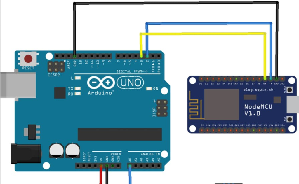
| Nodemcu | Arduino |
| RX | 3 |
| TX | 2 |
| GND | GND |
Final Verdict:
Here most important thing to note is Mongoose os doesn’t allow changing serial ports i.e. SoftwareSerial is not available in Mongoose OS. So we change the logging port of the ESP in configuration file i.e. mos.yml can do the trick.
If you are still facing issue regarding Serial Communication from NodeMCU using Mongoose OS to Arduino Feel free to Ask Doubts in the Comment Box Below and Don’t Forget to Follow us on 👍 Social Networks😉 Happy Splunking >


